Understanding the 858ssb Speech Clipper/Modulation Limiter
NEVER disable the modulation limiters in these rigs.
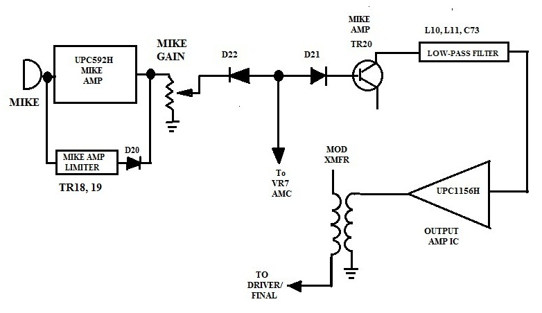
Look at the diagram of the 858 mike amp circuit below.
One of the unique features of the 858ssb chassis is the speech clipper/modulation limiter built into the mike amplifier circuit.The modulation control for this unit consists of two loops of automatic modulation control: One which controls the output of the mike preamp (IC3), and another which samples the output of the audio power amp and uses it to control the output of a pair of limiting (clipping) diodes.
The mike signal is applied to the input of the mike preamp (IC3). The signal is then highly amplified to several volts p-p and outputs at pin 8. The output is detected by D20 and this current is fed to the AMC transistors (tr19, tr18) which limits the preamp output by attenuating the mike signal at the preamp’s input. With a good stock handmike, the preamp output will be running at maximum almost all the time. For dxing, an unamplified microphone is the best setup, as background noise pickup is greatly reduced. For local operation, I like an amplified mike set up for voice frequencies (300hz to 3khz). Try one and you’ll see what I mean.
The output of IC3 is then fed to a pair of back-to-back clipping (limiting) diodes. In speech waveforms, the high amplitude peaks contain very little audio power. Using a diode clipper to remove these peaks results in a waveform with higher average power. Clipping distorts the signal, so the result is not exactly like the original. With the moderate clipping used in the 858 (about 10db) there is little loss of voice quality, but the audio power is increased dramatically. 10db of clipping results in a 4.5db increase in intelligibility at the receive end. A significant amount. With "deep" clipping (16-18db) there is a loss of naturalness, but the voice is highly intelligible. A clipping level of 18db provides a 8.5 db improvement over an unclipped signal at the receive end. This is what is needed to "punch-thru" in high traffic Dx conditions.
Back to the circuit.
The output of the clipping diodes is a 1.3 volt p-p (0.7v per diode) almost-squarewave. This signal is then reamplified by TR20 to a level sufficient to drive the audio power amp (IC4).The output of TR20 is filtered by the L10-L11 low-pass filter to remove the harmonics generated by the clipping. Forward biasing of the clipping diodes, and thus the base current of TR20, is set by R56-R104. D23 samples the output of IC4, and applies the current to AMC transistor TR23. The conduction point of TR23 is set by VR7, and the current sampled by D30 reduces the forward bias voltage of D21-22. This controls the base drive (and amplification) of TR20 which varies the output of IC4 (modulation). With VR7 set for maximum modulation, the diodes clip almost 100% of the time giving an AVERAGE modulation exceeding 80%.
Another excellent featureof this system is that the clipper functions in both AM and Ssb modes.
The ONLY way to improve on this system is to increase the clipping level from 10 to 18 db. This is done by inserting a variable resistor in the feedback loop of IC3. With a high drive input signal, adjust the resistor to increase IC3’s output until it just begins to flattop. Then slowly back it off until the flat topping disappears. On my rig, I used a relay to switch the resistor in/out, to allow me to use "deep" clipping only when I really need it.
-399
return to homepage
*